Friday 13 December 2013

Domain Specific Languages: Concept and Implementations in all 3 #UOITGameDev Projects

A Domain Specific Language (DSL)  is essentially a mini language which is designed to solve specific set of problems. In other words, with language like C++, the programmer can do almost anything they desire but with a DSL they can only do a finite list of similar tasks designed to solve one specific problem.

Example of what a DSL may look like. Source: GDC 2011 
This is an example of a DSL. This is just XML but the attribute names in the nodes all relate to a specific task, in this excerpt the DSL is describing a cutscene. We can see the name of the cutscene, start position, duration etc. Very simple, you can then simply parse this XML into your program and depending on the attribute names, treat the data correctly.

I have unknowingly actually created domain specific languages in all three of my years at UOITGameDev. Every year they’ve gotten better, this is because I always learn from the mistakes of the previous year.

Evolution of DSLs Over the Years


DSL used in first year project, Roboy
Look at this…trash. It kills me to say this but this is just awful. Back in first year this was my greatest accomplishment as a programmer. I created a level editor which allowed the user to place blocks where each block has a unique identifier (the first integer) and the X, Y position of the block (the second two integers, respectively). I say this is awful because, if I did not tell you what these numbers meant, you’d have no idea what they represented. Heck, I’m surprised I remember what these numbers mean.

First year level editor. You choose a block type, and place it on the grid.

In second year, we also made a level editor and this time our DSL has evolved quite a bit.

DSL in A Case of the Mondays, second year GDW game
As you can see above, instead of integers, we went with a straight up human readable format. This is better in my opnion because it allows everyone to be able to infer what these values mean.

Second year level editor. Horrible time sink. Limited functionality. But it got the job done.
Finally, the latest and greatest (so far): Roboy in the Hood. From our past experiences we knew that making level editors are huge time sinks, with minimal return. Going into this year we knew we wanted to use Maya as our editor, this would give us the ability to not only place objects but use Maya to bake in lighting effects and generate cube maps. Our DSL this year looks like this:

DSL used in Roboy in da Hood.

We have switched to an XML format this year. The data in this XML is used to construct the scene. Similarly to the previous years, we have to ability to output positions and rotations but this year we’ve added the ability to export materials and scripts. Below is a list of the current elements in our DSL. In the left hand column, you see the short hand notation used in Maya and on the right you see their respective meanings.

o, t, l, p
Object, trigger, Light, path. First character of model name in Maya to ID what a block of data is
-s, -d
Static, dynamic. Tag to denote if object is static or dynamic. Can only be used if data has object identifier.
mat, script, anim
Material, script, animation. Denotes which material, script or animation set a block of data should use. A block of data may have none, all or any combination of these components.

Since we used Maya as our level editor, we made it so the designer had to give the models specific names; these names are used by the exporter to generate nodes in the XML document. The XML document is then used by the importer to reconstruct the asset in game.

Application of our DSL in Maya.
In the image above, our block of data is named: o_truck_mattruck_scriptIceCream_d
This translates to: Object with a truck model, using a material named truck, with a script named IceCream that is a dynamic rigid body. Our importer and exporter has its own domain specific language which is used to help us identify data.

Translation of short hand notation used in Maya to DSL used by importer.

Now that you’ve seen some examples of domain specific languages, hopefully you see the usefulness in them. Imagine having to type out or export out a straight up C++ file containing the object placments in a game. Furthermore, by using DSLs, we are making the project more accessible to non-programmers.

 In all of my samples, I described setting up scenes, but why stop there? You can make a DSL to actually define gameplay elements for example:


Imagine making a script using these simple keywords. It wraps up all the calls to the low level functions into simple to use commands. This is beneficial because it allows non-programmers to write scripts and it also prevents people from messing up the low level functions that the game depends on.

Tuesday 10 December 2013

Guide to PhyreEngine Part III: Setting up Media Paths

This is the third and final part of my little “Guide to PhyreEngine” series of posts. The objective of this post is to describe how to set up local media directories for your project. I will begin by describing how the PhyreEngine samples handle this and explain why we may not want to do it like the samples. Note that there are tons of ways to do this and in this post I am describing how we did it.

Media Paths in the PhyreEngine Samples

Excerpt from the Asset XML file used in the Basic Sample
As mentioned in the previous post, the PhyreEngine uses an XML file to specify locations to assets. The assets listed in this XML file are converted to a platform specific binary format and the paths for the newly generated files are stored in a header file. In the line of code in the red box, you can see the name of the generated header file (“BasicAssets.h”) this header file is stored relative to your media directory. In the bit in the green box, you can see the path to the asset, relative to media directory.

Definition: Media directory, the directory where all of your assets are located.

As you can see by examining the file path to the asset, the asset in this sample are stored in a directory under the PhyreEngine install directory. For our project, we do not want to store our assets in this directory. We want to store our assets in a directory local to our project directory.

Setting Up a Local Media Directory

This is one of those things that is very simple and trivial to do, but required some figuring out. Let’s begin by creating some folders for our assets.

%ProjectDir%\src           //folder for source code
%ProjectDir%\media         //folder for assets
%ProjectDir%\media\models  //sub directory for models
%ProjectDir%\media\shaders //sub directory for shaders

You may want to make more sub directories for other types of assets but for the sake of simplicity, I will keep this guide to the bare minimums and use source from the Basic sample.

Using the project we set up from the first part of this guide, copy the following files into the, %ProjectDir%\src folder: (if you made any changes to them, make sure they are all vanilla)

%SCE_PHYRE%\Samples\Basic\Basic.cpp
%SCE_PHYRE%\Samples\Basic\Basic.h

Copy the following files into the %ProjectDir%\media folder.

%SCE_PHYRE%\Samples\Basic\Assets.xml    //stores file paths for assets
%SCE_PHYRE%\Media\PhyreAssetScript.lua  //black magic used by the PhyreAssetProcessor
%SCE_PHYRE%\Media\PhyreAssetSpec.xml  //Specs for the PhyreAssetProcessor, allows us to specify where binary files will be generated and what types of files to attempt to convert to binary

Copy all of the contents from: %SCE_PHYRE%\Media\Shaders to %ProjectDir%\media\shaders

Now that we have the bare minimums, we can modify them to suit our needs. Let’s begin by modifying Basic.cpp:
We just need to change one line of code which specifies the Media Directory for our project.

Vanilla Basic.cpp, currently the Media directory is set to the media directory in the PhyreEngine install path
As you can see in the above excerpt (shout out to well commented code!), the media directory is set to the PhyreEngine install directory (%SCE_PHYRE%), we want to set this to our local media directory. We do this by simply making the following change:

Modified Basic.cpp, now our project uses our local media folder
Now that we have set our media directory, we may specify our asset paths relative to this directory in the XML file.

Remember, ALL assets must be inside the media directory, so this means we just have to copy the assets from figure one into our local media directory and it will just work…right?


Before we can test this, we must set up our pre-build event which converts the asset to a binary platform. 

The easiest way to call a batch file, I don’t want to get in trouble posting SCE confidential code so I’ll try to describe how to create this batch file:

Copy the following file to your project directory:
%SCE_PHYRE%\Media\DonkeyTrader\ConvertDonkeyTraderAssetsForPlatform.bat

Open the file in NotePad and change it to say this:

Modified ConvertDonkeyTraderAssetsForPlatform.bat
Now we simply tell visual studio to call this batch file as a pre-build event:

Setting the Pre-Build Event in Visual Studio. Note this is only for the Win32GL platform with a Debug configuration, for other configurations see the Phyre documentation.

Now when we build our project, this command will be executed. Note that I am only showing you how to do this for Win32GL with a Debug configuration, I’m sure you can infer how to set this up for other platforms.

Anyways, if we try running the project, it will not work. Even though we put our Collada asset file in our media folder, it references other assets files (textures, shaders) which are not in our media folder. When assets reference other assets, it is important to make sure that all assets are in the media directory.

For simplicity, I will show how to export a simple cube in Maya:

Create a cube, right click on it and click add new material:


Add a collada Shader:


Now navigate to the shader’s attributes and set the shader.


We want to make sure our reference to the shader asset is relative, not absolute. There are two ways to do this. The sure-fire way would be to create an environment variable which stores your project’s directory and reference all of your assets using that variable or the shoddy way to do it is to use the “Set Project” option in Maya. For simplicity, I will show you the shoddy way, I call this the shoddy way because sometimes the paths are relative, sometimes they’re not. This is only an issue if you want to recompile the project on different computers, or if you move your project directory after you export an asset.


Click set project (shown above), navigate to your media directory and set the directory.

Now select the ColladaDefaultShader.cfgx located in your media directory, and export the model to the model folder in your media directory.

Now we just modify the XML file to use the cube we just exported and we should see it! Of course, since we are not exporting any lights, it will not be shaded but now that you have an asset loading, I’ll let you figure out the rest J.

Remember that this guide just showed the bare minimums to get started, for example, in my project I modified the PhyreAssetSpec.xml and the intermediate directory property to organize the generated data a bit better.

I hope that my "Guide to Phyre" series of posts was enough to give you a push in the right direction with PhyreEngine. I know when I had to figure this stuff out, the internet was pretty much useless, and it was up to me to figure everything out. 

Perhaps this isn't the best way or maybe you're still having troubles, if you have any questions or comments tweet me @MikeGameDev

Sunday 8 December 2013

Guide to PhyreEngine Part II: The Phyre Asset Pipeline

In the last post we ended with a window which rendered a solid blue screen. In this post I will outline what happens when you build a project and describe what must be done in order to load and render an object to the screen.

The Phyre Asset Pipeline

Models, textures, scripts and just about every other type of asset must be converted to the Phyre format. The .phyre files are platform specific binary versions of your asset. This is not unusual practice, for example Ogre does something similar with .mesh files which are binary versions of your mesh that Ogre can load. What is the point of converting assets to binary formats? To answer this you must understand what a binary file is.

Binary Objects

If you’ve ever opened up an asset file, such as a Collada .dae file you will see that it is human readable XML. This data is then parsed by the engine which looks for attribute names in the XML file and does something with it. If you do not serialize your data to a binary format this means the engine must parse this human readable data every time you start your program.

The best way to explain this (and almost anything!) is with a sample. Below I will describe how you would go about parsing a mesh in your day to day life.

Say you have a Wavefront .obj file. You export your mesh from Maya into an .obj file which contains a “mesh”. What is a mesh? A mesh is just a bunch of vertex positions and maybe you have normals and texture coordinates too but at the most basic level, you must have at least vertex positions. If you open the .obj file you will see something that looks like this:

Sample OBJ data, source: http://en.wikipedia.org/wiki/Wavefront_.obj_file


Notice what we have here? At the start we have identifiers, v for vertex and vt for texture coordinates etc. The simplest way to parse this data would be to scan the first letter in each line, do a string compare:

If (firstChar == “v”)
     vertices.push_back(loaded vertex)
if (firstChar ==”vt”)
     texCoords.push_back(loadedUV)

Assume loadedVertex is a simple struct which has four floats.

This is tedious as heck, but it works. We are loading each vertex and adding it to a list of vertices. This array of vertices is eventually thrown into a vertex buffer which is then sent to the GPU to render. If you do not serialize to binary, you have to do the whole string compare parsing process every single time. 

Every time you parse your data, you will end up with the exact same array which is sent to the GPU. This is very slow, imagine loading a mesh with thousands of vertices; this leads to an absurd amount of string comparisons (which are slow) furthermore, imagine you had to debug something and had to wait for this data to be parsed every time you ran the project. You’d go insane!

Binary serialization allows you to skip the whole text parsing process by essentially writing the array generated from the parsed data to a file. Then instead of parsing text every time, you can just load that array and It is up to the engine to do treat the data correctly. This is very fast because you are just taking a chunk of data from a file and putting it into memory. Of course, there is more to generating the array, different platforms may require different things to be done to the data, this is why Phyre must generate a different binary file for different platforms.

This is the basic idea behind binary formats. I know I’m not the best with words and what not but hopefully from this example you understand the idea and need for binary formats.

Back to Phyre, PhyreEngine generates it’s platform specific binary files as a pre-build event. Let me explain what this means:

PhyreEngine is a multiplatform engine, it supports windows with DirectX and OpenGL, bit, PS3 and PSVita. Depending on which platform you are building for, the engine will generate a binary .phyre file which is optimized for that platform. This is done in a build event. In my past experiences, when I clicked “build and run” Visual Studio would starting building MY project and run my game. PhyreEngine introduced me to the concept of “build events”.

What the heck is a build event? 

Pre-build events in Visual Studio. Note the red box, at different stages of the build you can choose to add additional tasks. The green box is the command to call the PhyreAssetGather tool, I will describe this in detail in the next post.

This means when you click “build” you can tell Visual Studio to do things before it starts running your project. As you can probably infer from the image above, you can tell Visual Studio to do intermediate task at different parts of the build process. PhyreEngine uses a pre-build event to call the AssetGather tool.

The AssetGather uses a .xml file which describes which assets need to be loaded as well as their file paths and generates a header file. Notice in the first line of the XML file below, there is a bit called “pathfix” this means all of your assets need to be under that directory. This directory is known as your media directory and you want all of your assets to be stored relative to that path. It is crucial that you do this because it will save a lot of headaches caused by assets not being found.

Excerpt from our asset XML file.

This XML file is processed and turned into a .h header file
Excerpt from the header generated from the XML file. Note that all assets have been converted to .phyre format. This header is included in our project and is used to load assets from disk. 
This is why the AssetGather tool must be run before your project can be built. This tool generates a header which your project includes. Essentially, you are including a header that does not exist when you click the build button for your project. It is generated as a pre-build event which occurs prior to the compiling of your code.

The AssetGather tool calls the AssetProcessor for each asset defined in the XML file. The AssetProcessor is a beast of its own and at this time I can only describe its interworking’s as black magic, fortunately PhyreEngine’s source is very well commented and one day I plan on looking into it.

Now that we have a better understanding of what the pipeline is like, we can move on in this guide. In the next post, I will demonstrate how to correctly set up your media directories and the pre-build events shown above.

Thursday 5 December 2013

Guide to PhyreEngine Part I: Setting up a Project

In this and the next few blog posts, I will outline every single step required to get started with the PhyreEngine from building a project to rendering an object on screen.

Before we start, I will begin with a little background:

Our professor warned us before we started our project that using PhyreEngine to develop our game would be a rough road, and let me tell you, he wasn’t kidding. The alternative to using PhyreEngine was using the 2LOC engine (created by a UOITGameDev grad). The 2LOC engine has a really handy “project generator” tool which automatically generates projects based on your configuration options, the project has all the dependencies and build configurations set for you. Unfortunately PhyreEngine does not have such a tool. This made something as trivial as setting up a project quite the challenge.

The 2LOC project generator
Creating a Phyre project is actually quite simple but took quite a bit of figuring out to accomplish. People always ask me “how is working with the PhyreEngine?” to which I reply “depressing.” Now don’t get me wrong, PhyreEngine great, but it is also a constant reminder of how much more I need to learn. Setting up a project was a challenge simply because there were a whole slew of concepts I did not know. In this post I will share the knowledge I gained from solving this problem and describe each of the steps required from setting up a project with the PhyreEngine, with pictures!

Note that we are using PhyreEngine 3.4.

Step One: Create a new visual studio project.


This step is pretty straight forward, just open up Visual Studio and create a new Win32 project. 


Make sure you start with an empty project.

Step two: Linking our project and solution with the PhyreCore and PhyreFramework


Right click on the solution and add the existing PhyreCore and PhyreFramework projects to the solution. This brings up the question, what is a solution? A solution is a sort of manager or container for projects. It simply maintains the dependencies between project. This brings up another question “what kind of dependencies are there between projects?” We’ll talk about those a little later.


Navigate to the PhyreCore project and add it. Repeat this process for the PhyreFramework.
Next we need to establish a relationship between the PhyreCore, framework and our project. This is done by making our project dependent of the projects we just added to our solution.

Step Three: Setting Project dependencies


Right click on our project and click project depandancies and references


Add PhyreCore and PhyreFramework to the dependancies.

In the build order tab, make sure your build order is:
PhyreCore
PhyreFramework
*Your Phyre Project*

You may not be able to build your project if is not in this order.

Now this next step may be redundant, but now I believe we need to add the PhyreCore and PhyreFramework as references to our project, I observed strange Intellisense behaviour when the projects weren't added as references…but then again when isn’t Intellisense exhibiting strange behavior?


Now that we have our project linked to the PhyreEngine, we need to set up our build configurations. This introduced me to the concept of property sheets. Normally when you set up a project, you need to go into your project settings and set which directories, libraries, pre-processor definitions manually. A property sheet will look at your current build configuration and automatically set these values for you.

This is an excerpt from the PhyreApp property sheet. Notice that the conditions are looking for the current platform the project is set to and is setting the additional library includes accordingly.

Step 4: Setting up Project Configurations

First we must open our configuration manager:


In the Edit Solution Platforms dialog box (under the active solution platform dropdown), we want to select the Win32 platform and rename it to Win32GL.


Next we want to set our Active Solution Configuration to Debug. Notice that the PhyreCore and PhyreFramework will automatically change to GLDebug, we want to make our project’s configuration also say GLDebug. We do this by creating a new configuration:


By creating our project configuration with this name, the project will use the PhyreApp property sheet to set the project properties up for us. Repeat this process for GLDebugOpt and GLRelease and for any other platforms you wish to support.

Once you set up your configurations, you need to actually tell the project to use the property sheet. This is done by opening the Property Manager (View > Other Windows > Property Manager), right clicking on the project and navigating to the directory below:


You want to add the PhyreCommon.props and PhyreApp.prop property sheets to your project.

Step Five: Clean up

Finally, all we need to do now is a little bit of clean up in our .vcxproj and .sln files. Currently, Visual Studio added the PhyreCore, PhyreFramework and the property sheets with absolute paths. This is bad, we want relative paths. I was not able to find a way to change this in Visual Studio, so we must use good ol’ NotePad++.

Open the .vcxproj file and search for any absolute paths and make them relative by using environment variables. An easy way to do this is by searching for “..\”. In the image below we see some nasty absolute paths. Note: depending on where your project is located, you may have a different absolute paths, so modify accordingly.
Exerpt from the Phyre project's vcxproj file. Note the ../../,  this is an absolute path meaning, if we were to share this project with teammates as is, they would have to put the project folder in the exact same directory we put it in.
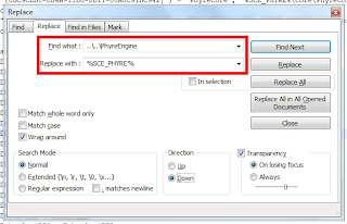
We can fix this by using the $(SCE_PHYRE) environment variable. The easiest way to do this is by using NotePad++’s find and replace feature.

Again, depending on where you created your project, the "Find what" value may be different for you. 
We must do the same thing for the .sln file. The syntax for environment variables is different in the .sln. You use the following:


Now we have nice clean relative paths:

Excerpt from the Phyre project's vcxproj file after modification. Note the we are now using environment variables,  this is a relative path meaning, if we were to share this project with teammates, they can put it anywhere they want on their computer.
Once you have set up the configurations for each of the platforms you wish to support, you may wish to delete unnecessary project configurations to clean up your configuration drop down menu. This is optional.

Currently our dropdown looks like this
We want it to look like this


You can remove all of these unnecessary configurations by going back into the configuration manager and deleting the Debug, DebugOpt and Release solution configurations.


Again, you may remove everything except for the Debug, DebugOpt and Release configurations. You may also do this same process to remove platforms you are not supporting.

At this point we should have all of our dependencies linked and once we add some code the project will be able to compile. To test this yourself, you can add the “basic.h” and “basic.cpp” source files to your project from the “Samples” folder in the Phyre install directory and comment out every line which has “s_loadedClusters” or “m_cluster” in it. This will give you a window with a blue color. If you do not comment these lines out, your application will crash instantly.

Now that we have a project which builds let’s load and render an object to the screen. This is easier said than done, in order to truly understand what happens when you click that build button, you must understand the Phyre asset pipeline, which I will cover in my next post.

Feel free to tweet me at @MikeGameDev if you see any problems or if you need any help, I'll try my best to help you out.

Thursday 28 November 2013

Navigation Mesh, Path Finding and Implementation in Resistance 3

Artificial intelligence is creating the illusion of intelligent agents.

In class we discussed that a navigation mesh is a simplified version of the complex level mesh. We also talked about Recast which is a handy tool that will import the mesh of your level and will create a nav mesh from that. Now how does it do that? The image below outlines the process at a very high level:

Figure 1: Recast's Navigation mesh generation algorithm. Source: Insomniac Game's GDC 2011
I wanted to talk about something that we sort of touched on in class but didn`t go into too much detail about: so you setup Recast, generate your Nav Mesh…now what?

What algorithms and data structures do you use to store this data and once you store this data, how do you use it to create “intelligent” agents?

You may say “just put it in a graph and traverse the graph using the A* algorithm”, and that’s correct but what type of graph implementation should you use and how do you implement A* traversal? In this post I will talk about a couple different ways to store graph data and the A* graph traversal algorithm. I will also briefly talk about Insomniac Game’s implantation of these things in Resistance 3.

Storing The Data

Well let’s reflect on the data we have from our nav mesh. We have nodes, which are the vertices which make up the triangles and edges which are the lines that connect the vertices together. Consider the following example:
How would you, the human capable of thought go from the green square to the red square? Nothing is blocking you so you would simply say “just go in a straight line”, which is absolutely correct. But the real question is how would the computer perform this task? The computer knows which node it is currently on (the green one) and which node it needs to get to (the red one) and that’s it. We must define a relationship between the nodes. These relationships are known as edges. An edge connects two nodes and defines that if I am on node X I may travel to node Y. The question now is how do we do this? Well we could just have a giant matrix and store Boolean values which specify whether two nodes are connected or not. This is known as an adjacency matrix.
Example of an adjacency matrix. Source: Programming Game AI by Example by Mat Buckland

In the example above, the matrix stores which nodes a given node is connected to and which nodes it isn’t connected too. A "1" defines that there is a valid connection and a "0" defines that there is not a valid connection. This is a perfectly valid data structure but it wastes quite a bit of memory. Another more memory efficient data structure are adjacency lists. Adjacency lists allow you to deduce the same relationship between nodes but use significantly less memory. This is done by simply storing which nodes a given node is connected too and making the assumption that any other node not on the adjacency list is not connected.


Example of an adjacency list. Source: Programming Game AI by Example by Mat Buckland

For each node, you must specify which nodes it is connected to. Storing an adjacency matrix for each node would be a memory massacre so use an adjacency list instead. Below is how you could go about storing your navigation data.

How I stored data for navigation in a past project
Each node has an ID which I use as an index into the two lists in the code above. For example: Data about Node 0 is stored in index 0 of the _nodes list and the adjacency list for Node 0 is stored in index 0 of the _edges list.

Traversing the Graph

Now that you have your data organized in a nice graph, you can finally traverse the graph. There are many algorithms to traverse a graph, if you are interested in learning about these algorithms I highly recommend the book “Programming Game AI By Example” by Mat Buckland, this book goes into great detail about each traversal method and provides excellent examples. The A* algorithm really is the best of the bunch, not only does it find the most efficient path from A to B, it’s also the fastest.
Suppose I place some obstacles in our example above:


The blue path is the most optimal route returned by the algorithm. Those red branches are all of the paths that the algorithm once considered. Clearly from this visualization, you should be able to see that the computer’s method of finding the most optimal path varies significantly from a human’s. The A* algorithm is a cost based search. This means each edge has a cost associated with it. It also means that the most optimal path may not necessarily be the one with the least amount of nodes.

Resistance 3

In the Insomniac Game’s GDC 2011 talk about navigation they discussed that the Recast library was used to generate their navigation meshes. Their usage of AI using navigation meshes is rather straight forward, it is outlined below:


First they are requesting and setting the requirements that an agent needs, then they are finding and smoothing a path. Smoothing a path is done to create a more natural movement of an agent as the follow a path. An exaggerated example of this can be seen below.

They are then using an obstacle avoidance steering behaviour to ensure the agent does not get stuck. The obstacle avoidance steering behaviour is not very difficult, you essentially just cast a sphere around your agent and test for collision, if there is no collision then carry on if there is the obstacle avoidance function will return a direction vector pointing away from the obstacle. Since steering behaviours can be summed together (via weighted average), if you are performing both avoidance and path following on an agent, the direction will point away from the obstacle and will still guide your agent to the next node in it’s path. In the most simple implementation of steering behaviours, this direction will be multiplied by your agent’s speed and therefore move your agent in that direction.

Since the agent is not just sliding along the path, its also animating so they may have special animations when specific obstacles are encountered. For example if there is a knee high obstacle, instead of making the agent awkwardly run around it, they may just play a “stepping over” animation.

I asked this question before, but I’ll ask it again: You the human see a knee high obstacle, what do you do? You just step over it. Now how will the computer know that an obstacle is knee high? The way Insomniac solved this problem was by having a designer go in and place identfiers on specific obsticales in the world and when an enemy encourters one of these identifiers, they would handle it accordingly. For example there is an enemy who is able to jump onto roof tops and there is another enemy who must go around. Both enemies use the same nav mesh, by placing identifiers around the world, and giving each AI a type, you could do a condition:

If (obstacleIdentifier == Building && agent.Type == roofJumper)
               agent.jumpOnRoof()
If (obstacleIdentifier == Building && agent.Type == roofJumper)
               agent.goAround()


Now ofcourse this is just a simple example, but hopefully it gets the point across.